Bending radius is one of the most critical parameters in underground fiber optic cable installation. Improper bending can cause microbending or macrobending losses, leading to signal attenuation, reduced transmission performance, or even permanent fiber damage.
In underground deployments, where cables are installed through trenches, ducts, and complex routing paths, maintaining the correct bending radius is essential for ensuring long-term network reliability.
For a complete understanding of underground fiber design, installation methods, and cable structures, refer to the guide on underground fiber optic cable engineering standards and deployment practices
What Is Fiber Optic Cable Bending Radius?
The bending radius refers to the minimum radius a fiber optic cable can be bent without causing damage or performance degradation.
It is typically expressed as a multiple of the cable’s outer diameter (OD).
Standard Rules:
- Static (installed) bending radius: 10 × cable diameter
- Dynamic (installation) bending radius: 15–20 × cable diameter
For example:
- Cable diameter: 10 mm
- Minimum static bending radius: 100 mm
- Minimum dynamic bending radius: 150–200 mm
Following these guidelines ensures that the optical fibers inside the cable are not subjected to excessive stress.
Why Bending Radius Matters in Underground Installation
Underground fiber cables are exposed to multiple stress factors during installation and long-term operation.
1. Preventing Signal Loss
Excessive bending can cause light leakage within the fiber, resulting in attenuation. This is especially critical in long-distance networks.
In large-scale deployments, engineers designing fiber optic cable solutions for long distance underground network transmission must carefully control bending conditions to maintain signal integrity.
2. Avoiding Permanent Fiber Damage
If the bending radius is too small, the glass fibers inside may crack or deform. Unlike mechanical damage, this type of failure may not be immediately visible but can degrade performance over time.
3. Maintaining Network Reliability
Improper bending during installation often leads to hidden faults that appear months or years later.
Many of these issues are categorized among common failure points in underground fiber optic cable systems
and can be avoided through proper installation practices.
Static vs Dynamic Bending Radius
Understanding the difference between static and dynamic bending radius is essential.
Dynamic Bending Radius
- Applies during installation
- Cable is under tension
- Requires larger radius (15–20× OD)
Static Bending Radius
- Applies after installation
- Cable is fixed in place
- Smaller radius acceptable (10× OD)
During trenching and cable pulling, installers must follow dynamic bending limits to prevent stress damage.
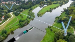
Bending Radius in Different Installation Methods
Direct Burial Installation
In direct burial, cables are placed directly in the soil. The trench path must avoid sharp turns.
When planning routes, engineers often consider direct buried fiber optic cable installation guidelines for underground projects to ensure smooth cable routing.
Duct Installation
In duct systems, bending occurs at:
- duct entry points
- manholes
- handholes
Proper duct design ensures gradual bends rather than sharp angles.
Urban Installations
Urban environments often involve tight routing conditions, making bending radius control more challenging.
Micro-trenching and conduit systems must be carefully designed to avoid excessive cable stress.
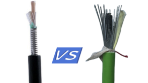
Impact of Cable Structure on Bending Radius
Different cable designs have different flexibility characteristics.
Non-Armored Cable
- More flexible
- Easier to install
- Smaller bending radius
Armored Cable
- Less flexible
- Requires larger bending radius
- Provides better mechanical protection
For example, cables designed with steel tape reinforcement require careful handling. Many projects use steel tape armored fiber optic cable for underground infrastructure protection which offers durability but reduces flexibility.
Bending Radius and Burial Conditions
Environmental conditions also affect bending requirements.
Soil Pressure
Heavy soil or compacted ground can force cables into tighter curves over time.
Temperature Changes
Thermal expansion and contraction may alter cable positioning.
Trench Design
Following proper burial depth requirements for underground fiber optic cable installation helps maintain stable cable positioning and reduces bending stress.
Installation Best Practices
To maintain correct bending radius during installation:
Avoid sharp turns in trench routes
Use large-radius rollers during cable pulling
Control pulling tension
Follow manufacturer specifications
Inspect cable routing before backfilling
Proper planning significantly reduces the risk of long-term performance issues.
How to Measure Bending Radius
Installers can estimate bending radius by measuring the curve formed by the cable.
Practical methods include:
- Using bending templates
- Measuring arc diameter
- Visual inspection during installation
In critical projects, inspection teams ensure compliance with engineering standards before completing installation.
Relationship Between Bending Radius and Installation Cost
Improper bending can increase project costs due to:
- signal loss troubleshooting
- cable replacement
- additional splicing
- service downtime
When evaluating budgets, engineers often consider total underground fiber optic cable installation cost factors and planning considerations to ensure proper installation practices are included in project planning.
Common Mistakes to Avoid
1. Ignoring Manufacturer Specifications
Each cable type has specific bending limits.
2. Tight Turns in Trenches
Sharp bends increase stress and risk of damage.
3. Over-Tension During Installation
Pulling cables too tightly reduces effective bending radius.
4. Improper Handling of Armored Cables
Armored cables require special care due to reduced flexibility.
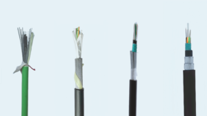
Product Considerations for Bending Performance
Cable selection plays a major role in bending performance.
High-quality outdoor cables are designed to balance:
- flexibility
- mechanical strength
- environmental resistance
In demanding installations, contractors often select durable outdoor armored fiber optic cable for underground deployment projects to ensure both protection and structural stability.
Conclusion
Bending radius is a fundamental parameter in underground fiber optic cable installation. Maintaining the correct radius prevents signal loss, avoids structural damage, and ensures long-term network reliability.
By understanding the differences between static and dynamic bending limits, selecting appropriate cable structures, and following proper installation practices, network engineers can significantly reduce the risk of failure in underground fiber systems.