Installing a fiber optic termination box is one of those jobs that looks simple on paper, but it’s easy to do poorly in the field. A box can be mounted perfectly and still fail later because fibers were routed too tightly, splices were stacked incorrectly, or the cable entry was never properly secured.
This guide walks through a practical, real-world installation process used in FTTH deployments. It covers not only mounting and splicing, but also how to plan port capacity, manage slack, label correctly, and avoid common installation mistakes.
If you’re working on an FTTH build, a building entry point, or an apartment corridor deployment, the steps below will help you achieve a clean and maintainable installation.
1) Confirm the Box Type Before You Install Anything
Before you drill holes, strip cables, or set up the splice tray, take 2 minutes to confirm the exact box type you’re working with.
In many FTTH projects, installers use the term “termination box” and “terminal box” interchangeably. In practice, most buyers searching for a ftth fiber optic terminal box are looking for the same enclosure type: a compact box designed for splicing, adapter termination, and fiber routing.
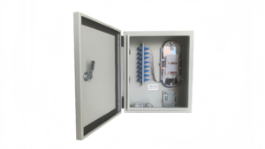
Common termination/terminal box configurations
- Adapter + pigtail splicing type (most common)
- Drop cable direct termination type
- Splitter-ready termination box (PLC inside)
- High-capacity MDU termination enclosure
Why this matters
The internal layout determines:
- how many splice sleeves you can store safely
- whether a PLC splitter can be mounted
- how port numbering should be planned
- what cable entry method is supported
2) Indoor vs Outdoor Installation: Choose the Correct Location
One of the biggest causes of long-term FTTH failures is using the wrong enclosure for the environment.
Indoor installation environment examples
- apartment corridors
- telecom riser rooms
- IDF closets
- building basements (dry area)
Outdoor installation environment examples
- building entrance walls
- poles (with brackets)
- fence-mounted enclosures
- wet or dusty basement zones
If the installation point is exposed to moisture, dust, or sunlight, you should treat it as an outdoor installation. Many projects specifically require a fiber optic terminal box outdoor enclosure with weather sealing and UV resistance.
For protected indoor corridors and telecom rooms, a compact fiber optic terminal box indoor style is usually more cost-effective and easier to maintain.
3) Tools and Materials You’ll Need
A professional termination box installation typically requires:
Fiber preparation and splicing tools
- fiber jacket stripper
- buffer tube slitter (for loose tube cables)
- fiber coating stripper
- lint-free wipes + isopropyl alcohol
- precision cleaver
- fusion splicer
- splice protection sleeves
- heat shrink oven (if separate)
Installation and finishing tools
- screwdrivers + drill
- wall anchors
- cable ties
- labeling stickers
- torque wrench (optional for outdoor gland tightening)
Testing tools
- VFL (visual fault locator)
- optical power meter + light source
- OTDR (recommended)
4) Step-by-Step: Mount the Termination Box
Step 4.1 Mark the mounting position
Good placement should achieve:
- easy technician access
- safe cable entry routing
- enough room to open the cover fully
- minimal bending at the entry point
A clean installation is more than “straight on the wall.” It should be installed so fibers naturally route without stress.
For a full overview of termination box installation practices across scenarios, refer to fiber termination box installation best practices.
Step 4.2 Drill and mount securely
Use wall anchors appropriate for:
- concrete
- brick
- drywall
- metal panels
For outdoor use, ensure the box is mounted flat and gasket surfaces remain even.
5) Cable Entry: The Most Ignored Step (But the Most Important)
The cable entry point is where most installation failures start. Even when splices are perfect, a poor entry will eventually cause:
- cable tension pulling on fibers
- sheath damage at the clamp
- microbending loss
- water ingress (outdoor)
- messy slack that cannot be reworked later
If you’re using a termination box with a bottom entry, make sure the cable route doesn’t force a sharp turn right after the entry point.
6) Strip the Cable and Prepare the Fibers
For loose tube outdoor cables
Typical steps:
- strip outer sheath
- expose strength member
- open buffer tube
- clean gel
- identify fiber colors
- route fibers to tray
For indoor tight-buffer cables
Typical steps:
- strip jacket
- expose aramid yarn
- trim and secure yarn
- route tight-buffer fibers
Pro tip: do not strip too much
Over-stripping causes slack storage problems. Under-stripping makes routing impossible.
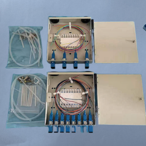
7) Plan Port Count and Capacity Before Splicing
This step is where many installations go wrong. A termination box might “support 8 cores,” but the real question is:
- How many fibers can be spliced cleanly?
- How many ports will be used today vs future?
- Is a splitter required?
- Is the tray layout designed for the port count?
For example, an installer may purchase a fiber optic terminal box 4 core unit, but later discover they actually need 4 ports + extra splicing space for feeder-to-distribution transitions.
Similarly, a fiber optic terminal box 8 core model may support 8 adapter ports, but only if tray routing is done correctly and slack is stored in controlled loops.
If your design is port-based rather than “core-based,” you may want to plan around a 4 port fiber optic terminal box instead of thinking only in fiber counts
8) Organize the Splice Tray Properly
A good splice tray layout should:
- keep splice sleeves aligned
- separate incoming and outgoing fibers
- maintain bend radius
- avoid stacking sleeves on top of each other
- allow future rework without chaos
Correct fiber routing habits
- route fibers through dedicated channels
- store slack as a smooth loop
- never cross fibers over the tray hinge
- keep splice sleeve positions consistent
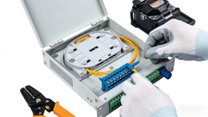
9) Fusion Splicing: Pigtails, Drop Fibers, or Both
Most FTTH termination boxes use pigtails (pre-connectorized fiber tails). You splice the pigtail to the distribution fiber, then plug the connector into an adapter port.
Standard fusion splicing process
- strip coating
- clean fiber
- cleave
- splice
- sleeve + heat shrink
- store sleeve in tray
Why pigtails are preferred
- faster field termination
- consistent connector quality
- easier testing and replacement
- less risk of poor field polishing
10) Install Adapters and Manage Patch Cord Routing
The adapter panel is the user-facing interface. Most FTTH projects use SC/APC adapters, but the important part is how you route patch cords or drop cables after termination.
Routing rules that prevent failures
- do not allow cords to pull downward sharply
- avoid tight loops near the adapter face
- ensure the cover closes without pinching cords
- keep the bend radius consistent
11) Installing a PLC Splitter Inside the Termination Box
If your termination box is splitter-ready, you can mount a PLC splitter inside.
Common splitter formats:
- mini type
- ABS module
- steel tube
A splitter-ready box is not just “bigger.” It must have:
- a stable splitter mounting area
- routing channels for input/output fibers
- enough slack storage space
For splitter-based FTTH designs, see termination box with PLC splitter for FTTH.
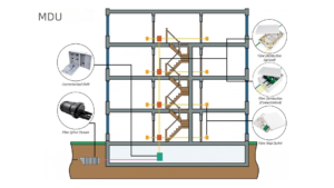
12) Apartment Buildings (MDU): Installation Tips That Actually Matter
MDU deployments are where termination boxes are installed most often, and also where mistakes become expensive.
In apartment buildings, the termination box must support:
- fast subscriber activation
- clear port mapping
- easy future expansion
- minimal disruption during maintenance
If your installation is inside a building corridor or telecom riser, you’ll want to follow guidelines for fiber termination box for apartment building FTTH deployments.
13) Labeling and Documentation (Don’t Skip It)
A termination box without labeling is basically a future service outage waiting to happen.
What to label
- port numbers
- floor/unit number
- feeder cable ID
- splitter ratio (if used)
- fiber color mapping
Why labeling saves money
Because when the network expands, the technician does not need to:
- unplug working customers
- re-trace fibers manually
- guess which port belongs to which unit
14) Testing After Installation
A professional installation should always include testing.
Recommended test sequence
- Visual inspection (bend radius, slack, pinch points)
- VFL check (optional but quick)
- Power meter test
- OTDR trace (recommended for documentation)
Typical issues found during testing
- dirty connectors
- poor cleaves causing high splice loss
- tight bends near the tray
- wrong port mapping
15) Common Installation Mistakes (Real-World)
Here are the most common problems installers run into:
Mistake 1: Overstuffing the splice tray
It may close today, but it will not be maintainable later.
Mistake 2: Sharp bends at cable entry
Microbending causes long-term loss.
Mistake 3: Poor strain relief
Cables pull on splices and crack sleeves.
Mistake 4: No labeling
Maintenance becomes slow and risky.
Mistake 5: Wrong enclosure type for environment
Indoor boxes fail outdoors.
16) Buyer FAQs: Price, HS Code, and Procurement Notes
This section is intentionally included because many engineers installing termination boxes are also responsible for sourcing materials.
What affects fiber optic terminal box price?
When buyers search fiber optic terminal box price, they usually want to compare boxes that look similar but perform very differently.
Key price factors include:
- material (ABS vs PC vs metal)
- sealing level (IP rating)
- port capacity and tray design
- splitter-ready design
- included accessories (adapters, pigtails, glands)
What is the HS code for fiber optic terminal box?
Many importers search fiber optic terminal box hs code because they need correct customs classification.
Tip: HS code classification may vary by country and whether the product is shipped as an empty plastic enclosure or as an assembled fiber optic distribution component.
What about region-specific demand?
Some customers search location-based terms like “Singapore,” but for B2B manufacturing websites, it’s usually better to focus on technical intent keywords (capacity, indoor/outdoor, splitter-ready).
17) Special Case: DIN Rail Mounted Terminal Boxes (Industrial Cabinets)
DIN rail mounted fiber optic terminal boxes are more common in industrial networks than in classic FTTH subscriber networks.
If you’re integrating fiber termination inside a control cabinet, you may encounter a din rail mounted fiber optic terminal box design instead of a wall-mounted enclosure.
For most apartment and residential FTTH builds, wall-mounted boxes remain the standard.
Conclusion
Installing a fiber optic termination box correctly is not just about mounting a box on the wall. It requires careful planning of port count, tray layout, cable entry, splicing, labeling, and testing.
A clean installation:
- reduces insertion loss
- improves reliability
- simplifies maintenance
- supports future expansion
- prevents costly service disruptions
Whether you’re installing an indoor FTTH terminal box in an apartment corridor, or an outdoor weatherproof enclosure at a building entry point, the same fundamentals apply: protect the fiber, manage slack properly, and keep the termination point service-friendly.