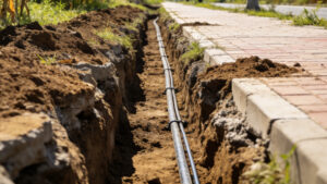
Determining the correct burial depth for underground fiber optic cable is not simply a matter of digging a trench and laying the cable. Burial depth directly impacts long-term reliability, mechanical protection, compliance with local codes, and future maintenance accessibility.
Improper depth is one of the most common causes of accidental cable strikes, frost-related stress, and long-term sheath damage. Whether the project involves rural broadband expansion, municipal backbone deployment, or residential FTTH connections, depth planning must be aligned with soil conditions, traffic loads, and installation methods.
For broader context on underground design strategies, trenching methods, and structural considerations, see the complete overview of underground fiber optic cable installation best practices
Standard Burial Depth Recommendations
Burial depth varies depending on installation type and environmental exposure. While regulations differ by country, the following ranges are widely adopted in telecommunications engineering.
1. Residential Yard Installations
For direct-buried fiber in residential areas:
- Typical depth: 12–24 inches (30–60 cm)
- Lawn or soft soil conditions
- Minimal vehicle load exposure
Shallow installations are common for FTTH drops, but reduced depth increases the risk of accidental damage during landscaping or future utility work. In these cases, warning tape placement 6–12 inches above the cable is strongly recommended.
2. Road Crossings
Under driveways or public roads:
- Recommended depth: 24–36 inches (60–90 cm)
- Often installed inside HDPE conduit
- Additional mechanical reinforcement required
Road crossings introduce compressive loads from traffic and potential soil compaction shifts. Conduit systems are typically used rather than direct burial to improve long-term resilience.
3. Agricultural and Rural Areas
In farmland or open rural routes:
- 30–42 inches (75–105 cm) is common
- Deeper burial protects against plowing equipment
Long-distance rural deployments often combine deeper trenching with armored cable structures to reduce rodent exposure and mechanical stress.
Direct Buried vs Conduit Depth Differences
Burial depth is also influenced by installation method.
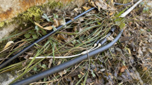
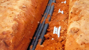
In direct buried fiber optic cable installation projects the cable itself must withstand soil pressure, moisture exposure, and potential external forces. As a result, depth tends to be slightly greater than conduit-based installations in comparable environments.
When conduit is used:
- The conduit absorbs mechanical stress
- Replacement or upgrades become easier
- Depth can sometimes be slightly reduced depending on regulation
However, conduit systems introduce additional cost and labor.
Minimum Depth for Code Compliance
Different regions define minimum cover depth standards for underground utilities. These are often governed by telecommunications authorities or civil engineering codes.
Common regulatory benchmarks include:
- 18 inches minimum for private property
- 24 inches minimum for public right-of-way
- 30+ inches under roadways
Before excavation begins, compliance with local excavation standards and utility separation requirements is mandatory. Violating depth regulations can result in costly rework and liability exposure.
Frost Line and Climate Considerations
In colder climates, burial depth must account for frost heave. When cable is installed above the frost line:
- Soil expansion can exert upward force
- Repeated freeze-thaw cycles may stress the cable jacket
- Long-term attenuation increases risk
For cold regions, trenching below the frost line is recommended. This can range from 36 inches to over 48 inches depending on latitude.
Frost-related stress is one reason why many contractors select steel tape armored structures in colder environments. Mechanical reinforcement reduces deformation risk when soil shifts occur.
Mechanical Protection vs Depth
Deeper burial is not always the most cost-effective solution. Protection can be achieved through:
- Armored cable design
- HDPE conduit systems
- Concrete encasement (high-risk zones)
- Marker tape installation
- Utility mapping and GIS documentation
For example, instead of exceeding 42 inches depth in rocky terrain, some engineers choose reinforced designs such as steel tape armored fiber optic cable for underground deployment which provides mechanical resistance without excessive excavation cost.
Separation from Other Utilities
Fiber optic cable must maintain minimum separation distance from:
- Electrical power lines
- Gas pipelines
- Water systems
- Sewer lines
Typical horizontal separation:
- 12 inches from low-voltage utilities
- 24 inches from high-voltage systems
Vertical separation is required when crossing other utilities, often with protective sleeves installed at intersection points.
Failure to maintain separation increases risk of electromagnetic interference (in specific environments), accidental strikes, and regulatory violations.
Trenching Methods and Depth Accuracy
Depth consistency depends heavily on excavation technique.
Open Trench Excavation
- High accuracy
- Suitable for urban areas
- Allows bedding layer preparation
Plowing Method
- Faster for rural routes
- Depth may fluctuate in uneven terrain
- Requires experienced operators
Horizontal Directional Drilling (HDD)
- Used under roads and waterways
- Depth controlled by drill path
- Ideal for minimizing surface disruption
In HDD projects, depth must be carefully planned to avoid existing infrastructure and ensure structural stability of the bore path.
Bedding and Backfill Considerations
Burial depth is only one part of structural protection. Proper trench preparation includes:
- 4–6 inches sand bedding layer
- Cable placement without sharp bends
- Warning tape installation
- Controlled backfill compaction
Excessive compaction directly above the cable can create compressive stress. Loose backfill, however, may result in settling and future surface depression.
Maintaining the proper minimum bending radius for underground fiber cable during trench installation is equally critical. Even when depth is correct, improper bending during placement can permanently affect optical performance.
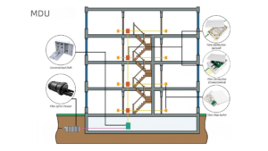
Depth for Long-Distance Backbone Routes
For metro backbone and intercity networks:
- 36–48 inches typical
- Often armored
- Installed inside high-density conduit banks
Long-haul routes prioritize durability over short-term installation savings. Soil stability, erosion risk, and future construction planning are evaluated during route engineering.
For extended deployments across varied terrain, selecting the best fiber cable for long distance underground networks helps ensure attenuation stability and mechanical resilience over decades.
Common Depth-Related Failures
Improper burial depth can lead to:
- Accidental excavation damage
- Rodent intrusion
- Soil erosion exposure
- Freeze-thaw stress
- Surface settlement
In many repair investigations, insufficient depth combined with lack of armoring is a primary cause of service disruption.
More broadly, recurring infrastructure issues in buried networks are examined in common underground fiber optic cable failure scenarios where depth, installation method, and structural design interact.
Depth Planning Checklist
Before installation:
Confirm local regulatory minimum depth
Identify frost line
Assess soil type (rocky, clay, sand)
Evaluate traffic load exposure
Determine installation method
Plan warning marker placement
Verify utility separation
A depth decision should always balance protection, cost, regulatory compliance, and future accessibility.
Conclusion
There is no universal burial depth that applies to all underground fiber optic installations. Residential FTTH projects may require as little as 12–18 inches, while backbone or roadway deployments often exceed 36 inches.
Correct burial depth must be determined by:
- Environmental conditions
- Load exposure
- Installation method
- Regulatory requirements
- Cable structure design
When combined with proper armoring, conduit protection, and accurate trenching practices, appropriate burial depth ensures decades of stable optical performance.