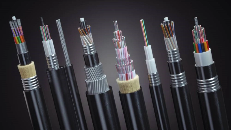
Choosing a fiber optic cable is not simply a matter of selecting the highest fiber count or the most heavily protected construction. The right cable depends on where it will be installed, how many fibers the network requires, what type of optical fiber is needed, how much mechanical protection is necessary, and how the cable will be installed and maintained.
For telecom operators, EPC contractors, ISPs, distributors, and infrastructure engineers, a good cable selection should satisfy the project requirements without adding unnecessary cost, weight, or installation complexity.
The most practical approach is to evaluate the cable in six steps:
- Installation environment
- Fiber count
- Single-mode or multimode fiber
- Armored or non-armored construction
- Cable construction
- Required specifications
This framework can be used for outdoor backbone networks, underground routes, aerial deployment, duct systems, FTTH infrastructure, industrial networks, and other fiber communication projects.
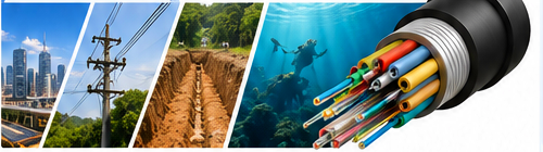
Quick Answer: How Do You Choose the Right Fiber Optic Cable?
The right fiber optic cable is determined by the combination of installation environment, fiber count, transmission requirements, mechanical protection, cable construction, and project specifications.

A simple selection sequence is:
| Project factor | Key question | Typical decision |
|---|---|---|
| Installation environment | Where will the cable be installed? | Duct, aerial, buried, underwater, indoor |
| Fiber count | How many fibers are required? | 12, 24, 48, 96, 144 cores, etc. |
| Fiber type | What transmission system is being used? | Single-mode or multimode |
| Mechanical protection | What external risks exist? | Armored or non-armored |
| Cable construction | What structure fits the installation? | Loose tube, tight buffer, central tube, stranded, etc. |
| Specifications | What does the project require? | Attenuation, tensile strength, crush resistance, bend radius, temperature, standards |
The important point is that these decisions are connected. For example, a 144-core cable for direct burial may require a very different construction from a 24-core cable installed inside a protected indoor pathway.
Start With the Installation Environment
The first question should always be:
Where will the fiber optic cable actually be installed?
Installation environment affects the required mechanical strength, weather resistance, water protection, cable construction, installation method, and maintenance strategy.
A cable designed for an indoor pathway should not automatically be used for direct burial. Likewise, an aerial cable must be designed for suspended loads, wind, span length, and environmental exposure.
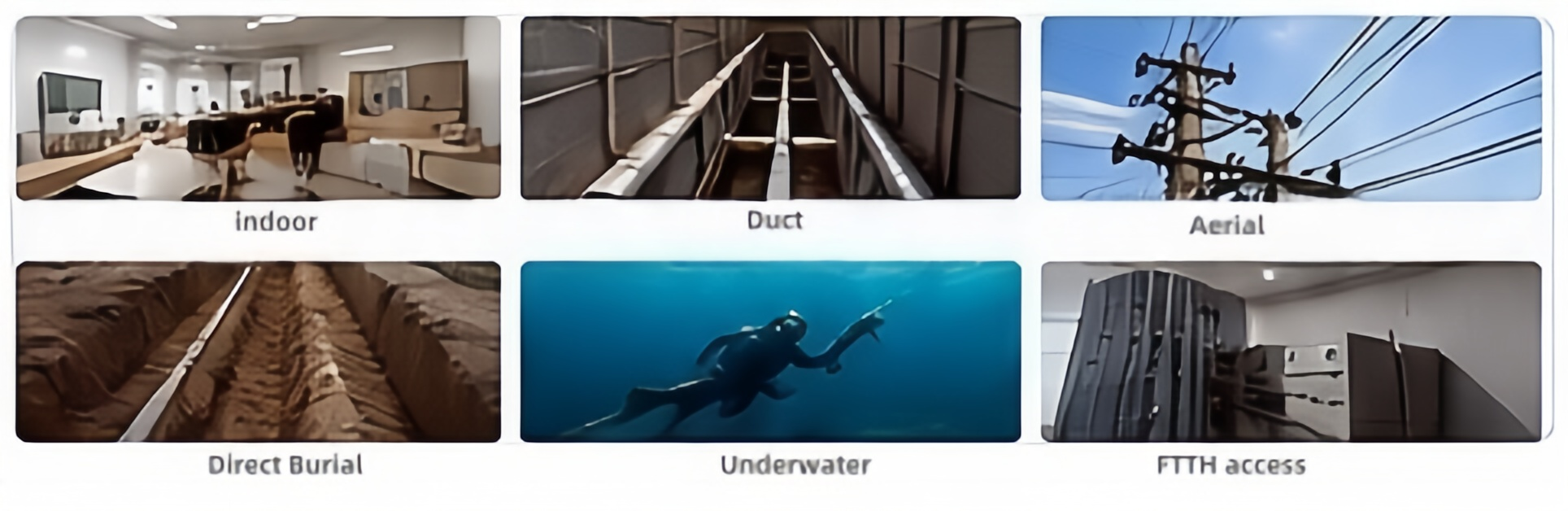
Common installation environments
| Installation environment | Typical cable considerations |
|---|---|
| Indoor | Flame performance, flexibility, bend performance, compact construction |
| Duct | Pulling/blowing performance, friction, diameter, water blocking |
| Aerial | Tensile strength, span length, sag, wind and weather resistance |
| Direct burial | Crush resistance, moisture protection, rodent/mechanical protection |
| Underwater | Water resistance, tensile strength, pressure and mechanical protection |
| FTTH access | Small diameter, flexibility, fiber count, easy installation |
For example, duct fiber optic cable is installed inside a conduit or duct system, so the surrounding duct provides part of the mechanical protection. Direct burial is different because the cable itself must withstand soil pressure, moisture, excavation risks, and other environmental stresses.
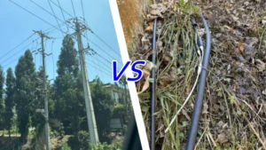
For overhead routes, the selection process must consider span length, pole or tower infrastructure, wind loading, and whether the cable is self-supporting. ADSS and Figure-8 constructions, for example, are designed around different support concepts.
When the main question is where the cable will be installed rather than which exact model to buy, the selection process can be narrowed by fiber optic cable installation environment.
Practical decision
- Existing underground conduit? Consider a duct cable.
- Pole or tower route? Consider an aerial cable such as ADSS or Figure-8.
- Cable will be placed directly in soil? Consider a direct-burial construction.
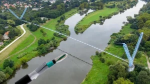
- River, lake, or underwater route? Consider an underwater/submarine construction.
- Inside buildings? Use an indoor-rated construction appropriate to the building environment.
Honelinks currently organizes its outdoor cable solutions around duct, aerial, direct burial, and underwater deployment, reflecting these different installation requirements.
For projects requiring outdoor deployment across different environments, the main product selection can be compared through outdoor fiber optic cable solutions.
Determine How Many Fibers You Actually Need
Once the installation environment is understood, the next question is fiber count.
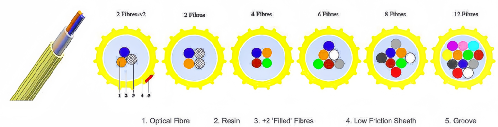
A fiber optic cable may be available in 12, 24, 48, 72, 96, 144 cores or other configurations. Choosing the lowest possible fiber count may reduce initial cost, but it can leave insufficient capacity for network expansion.
Choosing a much larger cable can provide more spare capacity, but it may increase cable diameter, weight, installation requirements, and cost.
The correct approach is to consider:
- Current active fibers
- Planned network growth
- Spare fibers
- Distribution architecture
- Future subscribers or connections
- Route importance
- Maintenance and restoration requirements
A simple fiber-count calculation
A useful planning model is:
Required fiber count = current fiber demand + future expansion capacity + spare fibers
For example, suppose a backbone route initially requires 32 working fibers.
If the project expects additional connections and wants spare capacity for maintenance, a 48-core cable may provide a more practical solution than a 36-core cable.
For a larger backbone route, 96 or 144 cores may be justified when future network expansion is expected.
The exact choice should come from the network design rather than from fiber count alone.
Fiber count should also match cable construction
Fiber count affects the physical design of the cable.
As the number of fibers increases, engineers may need to consider:
- Number of loose tubes
- Cable diameter
- Cable weight
- Bend radius
- Installation tension
- Duct filling ratio
- Drum length
- Handling and installation equipment
For example, Honelinks’ GYTA product is available in configurations including 12, 24, 48, 96, and 144 fibers, allowing the cable design to be matched to different network capacities.
For projects where the main question is whether 12, 24, 48, 96, or 144 fibers are appropriate, use a separate how many fiber cores do I need planning framework.
A useful rule
Do not select fiber count based only on today’s connections.
For long-life infrastructure, consider whether the cable will remain adequate when:
- More customers are connected
- New buildings are added
- Additional backbone routes are deployed
- Existing fibers need to be reserved for restoration
- Network architecture changes
A slightly larger fiber count can sometimes be more economical over the full service life of the network than replacing an undersized cable later.
Choose Single-Mode or Multimode Fiber
The next decision is the optical fiber itself.
For most long-distance telecom, FTTH, access, backbone, and outdoor infrastructure networks, single-mode fiber is the normal choice. Multimode fiber is more commonly associated with shorter-distance applications such as certain enterprise, data center, and local network environments.
The decision should consider:
- Transmission distance
- Required bandwidth
- Network application
- Active equipment
- Wavelength
- Future upgrades
- Total system cost
Single-mode vs multimode
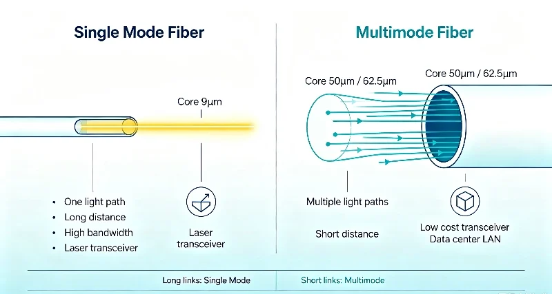
| Factor | Single-mode | Multimode |
|---|---|---|
| Typical distance | Long | Shorter |
| Core size | Small | Larger |
| Telecom backbone | Common | Less common |
| FTTH | Common | Rare |
| Data center | Common for longer links | Common for shorter links |
| Equipment | Depends on system | Depends on system |
| Future long-distance expansion | Strong option | More limited |
The most important mistake is choosing fiber based only on cable price.
The optical fiber must be compatible with the network’s transceivers and transmission architecture.
For example, a project using long-distance telecom links will normally require a single-mode fiber solution rather than choosing multimode simply because the cable appears cheaper.
When the decision is specifically between the two transmission modes, the relevant comparison is single mode vs multimode fiber for network applications .
What about G.652.D and G.657.A?
This is where fiber selection becomes more specific.
G.652.D and G.657.A are both single-mode fiber specifications, but they address different performance characteristics. G.657 fiber is designed for improved bending performance, while G.652 remains a fundamental choice for many conventional transmission networks.
However, the question of which fiber standard is appropriate should be separated from the basic single-mode vs multimode decision.
For detailed fiber standards and parameter selection, the relevant technical topic is fiber optic cable specifications and standards.
This separation keeps the selection article focused on the decision rather than turning it into a complete standards reference.
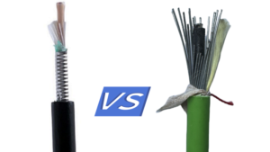
Decide Whether You Need Armored Fiber Optic Cable
Armor is not automatically better.
The correct question is:
What external mechanical risks does the cable need to withstand?
Armored construction adds protection, but it can also increase cable weight, diameter, stiffness, and installation requirements.
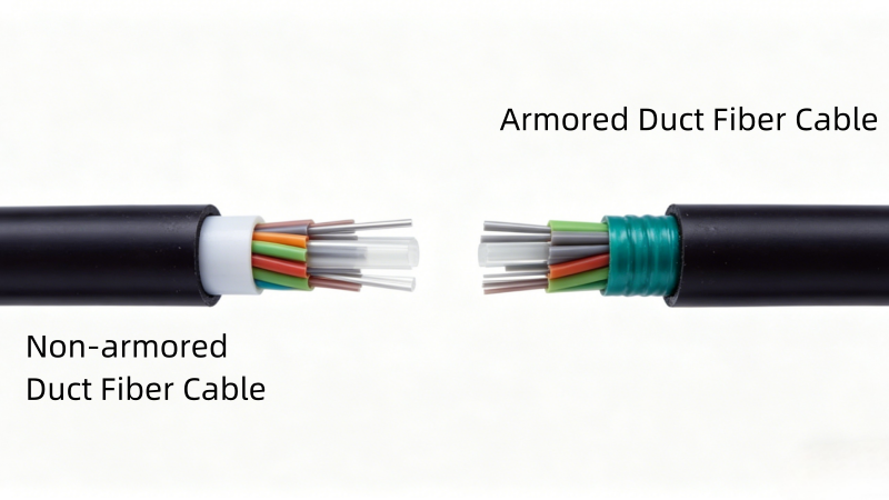
When armor may be appropriate
Armored fiber optic cable can be considered when the route has significant risks such as:
- Direct burial
- High crush loads
- Rodent activity
- Construction activity
- Industrial environments
- Rocky or difficult terrain
- Heavy mechanical exposure
- Certain underwater applications
For example, direct-burial systems require the cable itself to provide substantially more environmental and mechanical protection than a cable installed inside a protected conduit.
Honelinks’ direct-burial range includes single-armored GYTA/GYTS, double-armored GYTA53/GYTS53, and heavy-duty SWA constructions for different levels of underground protection.
When the project decision is specifically about protection level, use the comparison armored or non-armored fiber optic cable for outdoor networks.
Armor should match the risk
A useful engineering approach is:
| Project condition | Possible choice |
|---|---|
| Protected indoor route | Non-armored |
| Protected duct | Non-armored or light armored, depending on conditions |
| Standard underground route | Armored |
| Direct burial with higher mechanical risk | Heavier armored construction |
| Rodent-prone environment | Stronger mechanical protection |
| Heavy industrial environment | Heavy-duty armored construction |
| Electrically sensitive/high-voltage environment | Consider all-dielectric construction |
For electrically sensitive environments, the decision is not simply “armored or not armored.” A fully dielectric cable such as GYFTY can eliminate metallic components and provide advantages in high-voltage or EMI-sensitive areas.
For a fully dielectric outdoor construction, GYFTY non-metallic duct fiber optic cable is an example of a cable designed without metallic components.
Select the Right Cable Constructio
After deciding the environment, fiber count, fiber type, and protection level, the next step is choosing the physical cable construction.
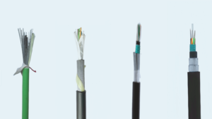
Two cables may contain the same type and number of optical fibers but perform very differently because their internal structures are different.
Common construction factors include:
- Loose tube or tight buffer
- Central tube or stranded loose tube
- Strength member
- Water-blocking system
- Armor
- Single or double sheath
- Outer jacket material
- Cable diameter
- Bend performance
Loose tube vs tight buffer
Loose tube construction provides the optical fibers with additional protection from mechanical and environmental stress and is widely used for outdoor cables.
Tight-buffered construction places a protective layer directly around the fiber and is common in indoor and specialized applications where easy handling and termination are important.
The right choice depends on the installation environment rather than on one construction being universally better.
Central tube vs stranded loose tube
Central-tube constructions can provide a compact design for lower or moderate fiber counts.
Stranded loose-tube constructions are useful when higher fiber counts and greater structural flexibility are required.
For example, Honelinks’ outdoor product range includes stranded loose-tube GYTA/GYTS constructions as well as central-tube GYXTW designs for different installation requirements.
For a deeper engineering explanation of internal layers, strength members, tubes, armor, and jackets, use fiber optic cable construction and internal structure.
Water blocking is another important consideration
Outdoor cables may need protection against longitudinal water migration.
Depending on the cable design, water-blocking can be provided by:
- Filling compound
- Water-blocking yarn
- Water-blocking tape
- Gel-filled loose tubes
- Multiple sheath and armor layers
The correct water-blocking system depends on the installation environment and project requirements.
For direct burial and harsh outdoor applications, the water-blocking system should be evaluated together with the armor and outer sheath rather than as an isolated feature.
Check the Fiber Optic Cable Specifications
At this stage, you should have a general cable concept.
The final step is checking whether the proposed cable actually meets the project’s technical requirements.
Important parameters can include:
- Fiber type
- Fiber count
- Attenuation
- Cable diameter
- Cable weight
- Tensile strength
- Crush resistance
- Minimum bend radius
- Operating temperature
- Installation temperature
- Water blocking
- Sheath material
- Armor type
- Applicable standards
These parameters should be evaluated as a complete system.
For example, a cable may have excellent tensile strength but be unnecessarily heavy for a particular duct installation. Another cable may have an attractive diameter but insufficient mechanical protection for direct burial.
Which specifications matter most?
The answer depends on the installation.
For an aerial cable, tensile strength, span conditions, sag, weather exposure, and appropriate hardware are important. For direct burial, crush resistance, moisture protection, mechanical protection, and soil conditions become more important.
For duct installation, cable diameter, friction, pulling tension, bending performance, and installation method may have greater influence.
When reviewing a manufacturer’s datasheet, the practical question is how to read fiber optic cable specifications and compare the values against the project requirement.
The datasheet should not be evaluated by looking at one impressive number. A technically suitable cable is one whose complete specification matches the installation method, network design, and applicable standards.
Fiber Optic Cable Selection Decision Tree
The selection process can be simplified into the following sequence:
Where will the cable be installed?
            │
     ┌──────┼────────┬─────────┐
     ↓      ↓        ↓         ↓
   Duct   Aerial   Buried   Underwater
     │      │        │         │
     └──────┴────────┴─────────┘
                    ↓
             How many fibers?
                    ↓
          Single-mode or multimode?
                    ↓
             Armor required?
                    ↓
          Which cable construction?
                    ↓
          Check technical specifications
                    ↓
            Select cable design
This approach is more reliable than starting with a product model.
The product model should be the result of the selection process, not the starting point.
Example: Selecting a Cable for a Direct-Burial Backbone
Consider a hypothetical telecom backbone project with the following conditions:
- Outdoor installation
- Direct burial
- Long-distance transmission
- 96 fibers required
- High mechanical risk
- Long service life expected
- Future network expansion required
The selection process would look like this:
Step 1 — Environment
Direct burial means the cable will not have a protective conduit around it.
→ A direct-burial construction is required.
Step 2 — Fiber count
The network requires 96 working fibers with additional capacity.
→ A 96-core or higher-capacity cable should be evaluated.
Step 3 — Fiber type
The route is long-distance telecom infrastructure.
→ Single-mode fiber is the logical starting point.
Step 4 — Mechanical protection
The cable will be directly buried and exposed to external mechanical risks.
→ Armored construction should be evaluated.
Step 5 — Construction
A stranded loose-tube construction can provide a practical structure for higher fiber counts and outdoor deployment.
Step 6 — Specifications
The final comparison should include:
- Attenuation
- Tensile strength
- Crush resistance
- Bend radius
- Water blocking
- Cable diameter
- Weight
- Temperature range
- Applicable standards
A cable such as a GYTA53/GYTS53-type double-armored construction may then be considered when the project requires higher underground protection. Honelinks describes these constructions as double-jacket, armored solutions for harsher underground environments.
The important point is that the product was selected after the project conditions were defined.
Common Fiber Optic Cable Selection Mistakes
Choosing by price alone
The cheapest cable may not be the lowest-cost solution over the entire project life.
An unsuitable cable can increase:
- Installation difficulty
- Cable damage risk
- Maintenance requirements
- Replacement cost
- Network downtime
Choosing too much protection
The opposite mistake is also common.
A heavy armored cable is not automatically the best choice for a protected duct or indoor pathway.
Excessive armor can increase:
- Cable weight
- Diameter
- Material cost
- Handling difficulty
- Installation requirements
The goal is adequate protection, not maximum protection.
Choosing fiber count based only on current demand
A cable that exactly matches today’s requirements may become insufficient as the network expands.
For infrastructure projects with a long service life, future capacity should be considered during initial cable selection.
Ignoring installation method
The same cable may behave differently depending on whether it is pulled, blown, buried, suspended, or installed underwater.
Installation forces should therefore be considered during cable selection, not after the product has already been purchased.
Looking at only one specification
A high tensile rating does not automatically make a cable suitable for every application.
Cable selection should consider the complete specification and how each parameter relates to the installation environment.
Fiber Optic Cable Selection Checklist
Before approving a cable for a project, confirm the following:
Installation
- Indoor, duct, aerial, direct burial, or underwater?
- What installation method will be used?
- What environmental exposure is expected?
Optical requirements
- Required fiber count?
- Single-mode or multimode?
- Required fiber specification?
- Required attenuation?
Mechanical requirements
- Is armor required?
- Required tensile strength?
- Required crush resistance?
- Required bend radius?
- Rodent or impact risk?
Environmental requirements
- Water blocking required?
- UV exposure?
- Operating temperature?
- Chemical or industrial exposure?
- Electrical/EMI considerations?
Project requirements
- Applicable standards?
- Cable diameter limitations?
- Maximum cable weight?
- Required drum length?
- Future expansion requirements?
- Required certifications or market-specific compliance?
If these questions have clear answers, the cable selection becomes much more straightforward.
Final Fiber Optic Cable Selection Framework
The right fiber optic cable is not determined by one specification or one product name.
A reliable selection process follows this order:
1. Installation environment
Determine whether the cable will be installed indoors, in ducts, overhead, underground, or underwater.
2. Fiber count
Calculate current requirements, future expansion, and spare capacity.
3. Fiber type
Select single-mode or multimode based on transmission distance, network architecture, and equipment.
4. Mechanical protection
Determine whether non-armored, light-armored, double-armored, or heavy-duty construction is appropriate.
5. Cable construction
Evaluate loose tube, tight buffer, central tube, stranded construction, strength members, water blocking, and sheath design.
6. Technical specifications
Verify attenuation, tensile strength, crush resistance, bend radius, temperature, dimensions, standards, and other project requirements.
Only after these six steps should you select the specific cable model.
For example, Honelinks’ outdoor portfolio includes GYTA, GYTS, GYTA53, GYTS53, GYFTY, GYXTW, aerial ADSS and Figure-8 constructions, and underwater armored solutions, allowing cable structure to be matched to different deployment conditions.
The same selection logic can also be applied when a project requires a customized fiber optic cable rather than a standard catalog construction.
For example, a project requiring a combination of fiber count, fiber type, armor, strength member, sheath, and environmental performance can be evaluated against a specific GYTA aluminum armored fiber optic cable construction.
The key is to start with the project requirements and work toward the cable design—not start with a cable model and try to make it fit the project.

 English
  Español